Teo
Brown

Mechanical engineering student at the University of Georgia. I build robot hardware: a spherical gear wrist, a micromouse drive, a teleop arm, and the FEA to check them.

Click a project card. The arm brings it to you.

ARM 01 / liveIdle

Projects

Four builds, with the numbers

01
Undergraduate research

Spherical gear wrist

A 3D printed ball-joint wrist for a robot hand, and the question of which printable material it should be made from.

Role
Undergraduate researcher
Lab
Dr. Hongyue Sun, UGA
Dates
Aug 2026 to present
Tools
MuJoCo, Python, SolidWorks, Bambu Lab printers

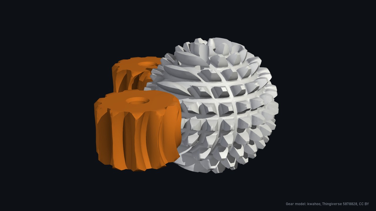
ABENICS is a joint mechanism that mimics a ball joint. Two monopole gears drive a cross spherical gear, so the joint turns about all three axes. My research uses it as a robot wrist. I wrote a SolidWorks script that generates both gears from the ABENICS paper, and printed a PLA set to confirm that two monopole gears mesh with one cross gear.

To get the load, I put a UR5e arm with an AmazingHand in MuJoCo and ran a full pick-and-place cycle with a torque sensor at the wrist. The static hand calc gives 0.0886 N-m. Motion adds 7.7 percent, so the 0.0954 N-m peak became the design load.

Then single-tooth FEA: the motor gear pushes one tooth until each of four printed materials reaches its strength, checked along and across the printed layers. The weakest case, PETG HF across its layers, still holds 6.8 times the peak load.

Next: tensile bars printed on the lab's printer, then the FEA again with measured properties. A SolidWorks rig that loads 20 gear sets to failure is in design.
0.0954N-mpeak wrist torque in the sim
6.8xlowest safety factor, PETG HF across layers
4printed materials compared
The ABENICS gear set. Gear model: kwahoo, Thingiverse 5878828, CC BY.
MuJoCo: wrist torque through a pick-and-place cycle, against the static calc.
FEA: one tooth loaded until each material reaches its strength.
02
Research tool

Layer-aware FEA

FEA for 3D printed parts that reads the printer's G-code, so it knows where the layers are.

My role
Designed the approach and test plan, directed the build, verified each phase
Built with
Python, CalculiX, PyVista
Dates
Oct 2026
Status
Verified, not yet validated

Standard FEA treats a printed part as one solid material. A real print is stronger along its printed lines than across its layers, and its infill is mostly air. I proposed building the model straight from the sliced G-code. Every element gets its layer, its line directions and how full it is. CalculiX solves it, and each line direction is checked for breaking within a layer or between layers.

On a 24-tooth spur gear printed standing on its teeth, the tooth pointing up splits between layers at about 12.4 N. Standard FEA says 15.5 N, and it can't tell that tooth from one on the side, which cracks through a layer instead.

It passes 44 of 44 verification cases against hand calcs, with the limits written down before the first run. Those checks caught a solver bug: CalculiX's multithreaded solver gave wrong answers in 10 of 24 repeat runs, with no error. Every run now uses a different solver and rejects any solve whose forces don't balance.

The material constants are datasheet placeholders until my coupon tests, so these forces test the method, not the parts.

44/ 44verification cases within limits
12.4Nlayers split, vs 15.5 N from standard FEA
427printed layers read from the G-code
The spur gear rebuilt line by line from its sliced G-code.
Gear tooth test: hub held, top tooth pushed until the layers split.
ISO 178 bar printed standing up: layers separate at 64.6 N.
The same bar printed flat, loaded at 30 percent of the span.
03
IEEE Micromouse, UGA

Bulldog Byte V3

The drive module for our maze-solving robot, from CAD to the bench.

Role
Mechanical team lead
Team
IEEE Micromouse, UGA
Dates
Aug 2025 to present
Tools
Fusion 360, KiCad, 3D printing

A micromouse is a small robot that solves a maze on its own. I designed our drive module: two Faulhaber 1717 DC motors share one printed mount, and a 16-tooth pinion on each motor drives two 60-tooth spur gears, one per wheel.

I picked the drivetrain by testing gear contact ratio, gear material and heat transfer between materials. I designed more than five of the robot's main parts in Fusion 360 and worked with the electrical team on the PCB in KiCad.

The skid plate under the PCB took the most iteration. After three printed versions of a friction slider, I replaced it with a rolling ball.

3.75: 160T spur over 16T pinion
2motorsfour driven wheels, one printed mount
80+applicants for a three-person mechanical team
Exploded drive module, from motor to tire.
Each pinion drives two spur gears. Wheels drawn see-through.
Bench test on the lab supply. Real hardware; unmute for the motors.
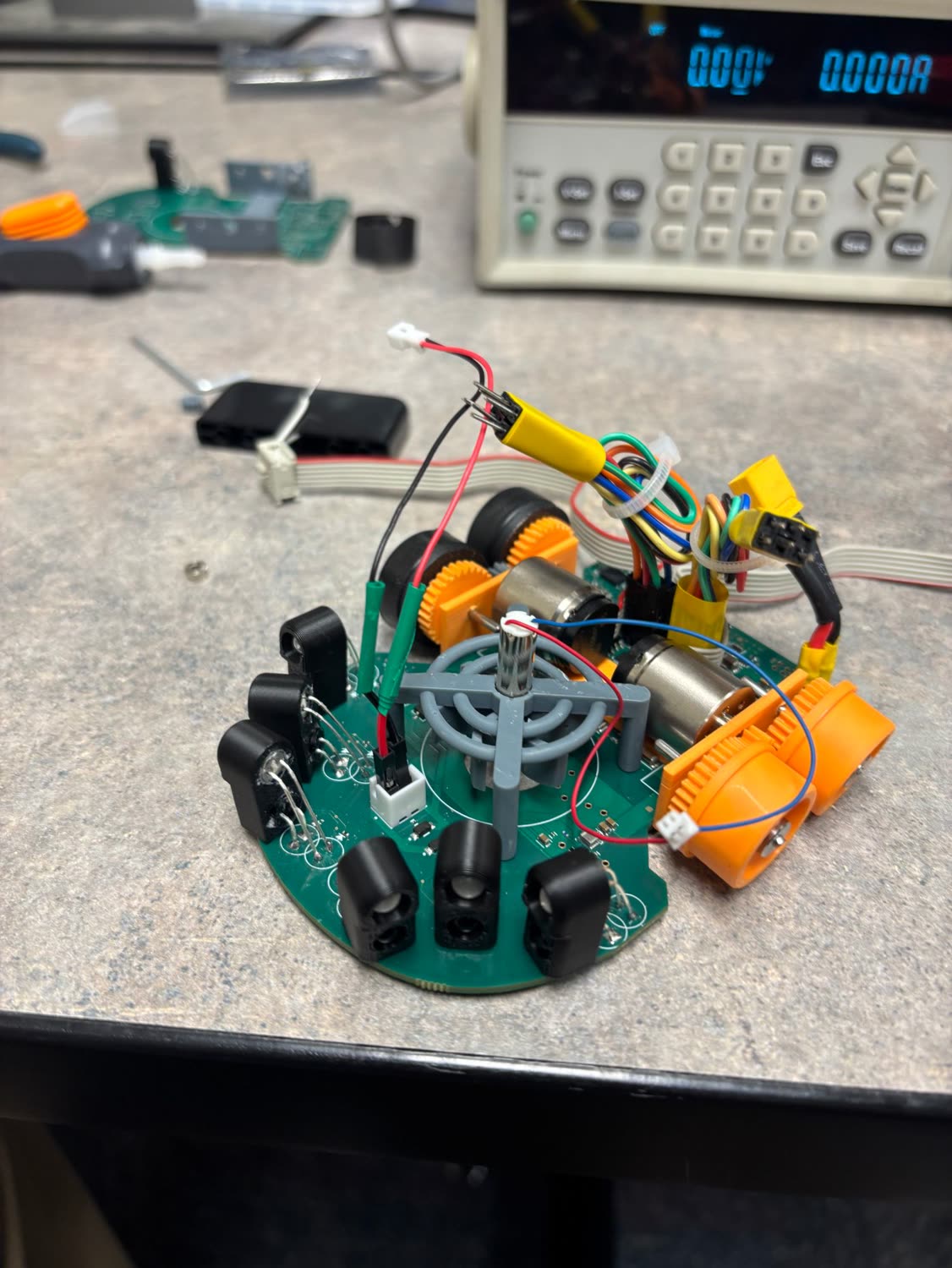
The assembled micromouse on a lab bench, with orange printed drive modules and black wall sensors
The built mouse: drive modules, center fan and wall sensors.
The full V3 assembly, from the team's Fusion 360 file.
04
Research pilot task

GELLO teleop arm

A hand-held copy of a UR5 that drives the real robot.

Role
Builder
Where
University of Georgia
Dates
Jan to May 2026
Tools
DYNAMIXEL servos, DYNAMIXEL Wizard, 3D printing

GELLO is UC Berkeley's open-source teleoperation controller: a scaled copy of the robot arm made from printed parts and DYNAMIXEL servos. Move it by hand and the real arm follows.

I printed and assembled one for the lab's UR5 and designed its servo mounts and cable routing. I set the seven servo IDs 1 to 7 from base to gripper, then calibrated each joint's offset so the same pose on the GELLO means the same pose on the robot.

1234567 BaseShoulderElbowWrist 1Wrist 2Wrist 3Gripper
Servo ID and the UR5 joint it drives.
The idea, simulated in MuJoCo: a GELLO-style leader arm drives a UR5e. This is a simulation, not my physical build.
Two GELLOs driving two UR5 arms. Clip from the GELLO project page, P. Wu et al., UC Berkeley.
About

Teo Brown

I'm a mechanical engineering student at the University of Georgia, graduating in May 2029 with a 3.96 GPA. I work on robot hardware: undergraduate research on a spherical gear wrist under Dr. Hongyue Sun, and the drive module for UGA's IEEE Micromouse team, where I lead the mechanical side.

I also co-founded Framewright Consulting, which builds custom AI agents and workflows for businesses.

Looking for a 2027 internship or co-op in mechanical or robotics engineering. Happy to relocate.

  • Aug 2026 to presentUndergraduate researcherUniversity of Georgia, Dr. Hongyue Sun
  • Aug 2026 to presentCo-founderFramewright Consulting LLC, Athens, GA
  • Dec 2025 to presentSenior reviewerHandshake AI, reviewing AI training tasks for GIMP, Krita and Inkscape
  • Aug 2025 to presentMechanical team leadIEEE Micromouse, UGA
  • Jan to May 2025Engineering internAEC Engineering, Roswell, GA. Standardized CAD file organization and revision control, which cut design review time 20 percent.
  • Aug to Dec 2024Engineering internDMD Engineering / PE Structures and Associates, Norcross, GA. Delivered 15+ AutoCAD drawing sets.
CAD and drawings
SolidWorks (CSWA), Fusion 360, Inventor, AutoCAD, Civil 3D, KiCad, GD&T
Fabrication
TIG welding, CNC machining, Formlabs resin printing, FFF 3D printing
Analysis
FEA, CalculiX, MuJoCo, hand calculations, tolerance stack-ups
Code
Python, MATLAB
Robotics
DC motors, DYNAMIXEL servos, joint mapping to a UR5, teleoperation
Certifications
SolidWorks CSWA, OSHA 10-Hour
Contact

Get in touch